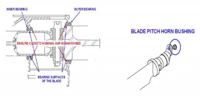
Stiff Pedals Experienced in Certain Flight Situations – EC130
A couple operators have reported experiencing tail rotor pedal stiffness when hovering or in very low speed flight with a quartering tail-wind. The situation is relieved by pushing hard through the stiffness or increasing forward airspeed.
Troubleshooting has revealed that the stiffness is caused by the radial clearance between the tail rotor inner and outer bearing surfaces and the bearings being too great. When the radial gap is allowed to be at or near the maximum tolerance, it is believed that the blades can be displaced angularly in the bearings, which added to aerodynamic loads, causes extra friction which is felt by the pilot as pedal stiffness.
Ensure that in service, the radial clearance is maintained close to nominal as directed by AMM 64-21-00, 6-1. By maintaining the Graphoil thickness on the bearing surface of the blade and ensuring that the bearings are not overly worn, the nominal radial gap will be maintained and stiffness in the pedals will not be experienced.
As a reminder – do not forget the blade pitch horn bushings – they must also be monitored for wear and replaced as required.
Starter / Generator Wiring – AS350/EC130
In the past, it has been brought to our attention that a few aircraft were experiencing slow starts during the starting procedure of the helicopter. After troubleshooting was carried out it was found that two of the large gauge wires of the Starter / Generator (S/G) wire harness were installed in the incorrect positions at the S/G terminal strip.
As a reminder for this potential snag, the terminals on the S/G from top to bottom are D – C –B – E – A. The middle three terminals have the large gauge wires connected to them.
Always be sure to confirm with the Wiring Diagram Manual in chapter 24 for your connections. If the labels on the wire harness are not clear, or have been removed, a quick continuity check will confirm the final destination of the wires. They are as follows:
- Connection “C” goes to the Start Relay inside the Master Electrical Box (MEB), which is the 2nd “can style” relay from the right hand side of the MEB
- Connection “B” goes to the Generator Relay inside the MEB, which is the 1st “can style” relay from the right hand side inside the MEB
- Connection “E” goes to the ground connection, identified as 5N, located underneath the right hand side foot well
We hope this will serve as a good reminder to never underestimate the way of the electron, and to keep those electrons flowing in the correct direction!


